
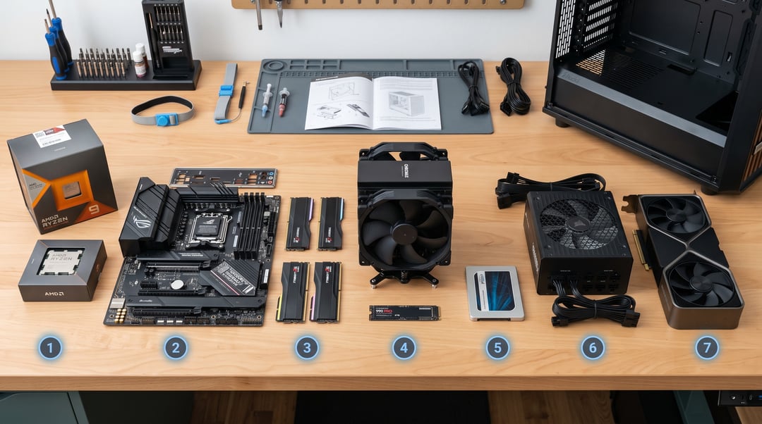
You've researched every component, checked compatibility, and finally have all the boxes in front of you. Now comes the part that makes first-time builders nervous: figuring out how to install PC components without breaking anything or having to disassemble half the build to fix a mistake.
The order matters more than most guides admit. Install the CPU after the motherboard is already in the case, and you're working in a cramped space with poor angles. Skip the I/O shield, and you'll need to pull everything back out. Route power cables after installing the GPU, and you'll be fighting for space and airflow.
This guide walks through the correct sequence, from workspace prep to first boot, so you can build methodically without backtracking.
Prepare your workspace and ground yourself
Clear a large, flat surface where you can spread out parts and manuals without clutter. Good overhead lighting matters more than you'd expect when you're trying to align tiny pins or find the right header on a motherboard.
Remove both side panels from your case and set them aside. Place the motherboard box on your workspace and keep it there—the foam padding inside makes an ideal non-conductive surface for assembling the CPU, cooler, and memory before you mount the board in the case.
Static discharge can damage components even if you don't feel the shock. Before touching anything, ground yourself by touching an unpainted metal part of the case, like the bare steel on the inside of the PSU shroud. If you have an antistatic wrist strap, clip it to the case frame and wear it throughout the build.
Keep the motherboard manual and case manual within arm's reach. You'll refer to both constantly for header locations, screw types, and connector pinouts. A magnetic-tip screwdriver prevents dropped screws from disappearing into case crevices.
Install the I/O shield and mount the motherboard standoffs
Start by snapping the I/O shield into the rectangular cutout at the back of the case. Push it from the inside until all four edges click into place. The metal tabs should face inward toward the motherboard, not outward into the case interior. If it pops out while you press one side, apply firm, even pressure across the entire perimeter.
Next, install the motherboard standoffs. These brass or metal spacers screw into the case's motherboard tray and prevent the board from touching bare metal, which would cause a short circuit. Check your motherboard manual to see which form factor you have—ATX, Micro-ATX, or Mini-ITX—because each uses a different hole pattern.
Line up your motherboard over the tray without setting it down. Note which holes align with threaded holes in the case, then screw a standoff into each matching position. Hand-tighten them snug but not torqued down. Cross-threading or overtightening can strip the soft metal threads.
Never install standoffs where there's no corresponding motherboard hole. An extra standoff touching a solder point or trace on the back of the board will short it the moment you power on.
Install the CPU, cooler, and RAM outside the case
Place the motherboard on top of its cardboard box to give yourself a stable, non-conductive surface. Open the CPU socket by lifting the retention arm until it stops. Modern Intel sockets have a metal cover that lifts with the arm; AMD AM4 and AM5 sockets expose the pin grid or land grid directly.
Align the CPU using the corner notches on Intel chips or the gold triangle marker on AMD processors. These match corresponding indicators on the socket. Lower the CPU straight down without pressing. It should drop into place by gravity alone. Close the retention arm. It will take real force to latch on Intel boards, which is normal.
Check whether your cooler has thermal paste pre-applied. If not, apply a pea-sized dot to the center of the CPU. Mount the cooler according to its instructions. Tower coolers typically use a backplate and screws; AIO liquid coolers may require bracket swaps. Route the fan cable to the CPU_FAN header on the motherboard.
Insert RAM into slots 2 and 4 when using two sticks. This configuration runs dual-channel on most boards. Press down firmly until both retention clips snap shut.
Mount the motherboard and connect front-panel headers
Lower the motherboard into the case at an angle, sliding the rear I/O ports into the shield opening first. Once the ports are seated, flatten the board so the screw holes align with the standoffs. If a hole doesn't line up with a standoff, don't force it. Remove the board, adjust the standoff positions, and try again.
Install screws in a star or cross pattern rather than working around the perimeter. This distributes pressure evenly and prevents the board from warping. Tighten each screw until it stops easily, then give it a quarter turn. The board should sit flat without flex, but overtightening can crack the PCB.
Connect the front-panel headers next. These small plugs run from the case's power button, reset button, and LEDs to a cluster of pins on the motherboard, usually labeled along the bottom edge. Your motherboard manual has a diagram showing which pins correspond to power switch, reset, power LED, and HDD LED. Power and reset switches have no polarity, but LED connectors do. The positive wire is typically marked or colored, and reversing it means the light won't work.
Install storage drives and the GPU
M.2 drives mount directly to the motherboard. Locate the M.2 slot (check your motherboard manual if you have multiple slots, as they may support different speeds). Remove the small screw at the end of the slot, insert the drive at a 30-degree angle, then press it flat and secure it with the screw and standoff. Some boards include a heatsink cover that screws down over the drive.
For 2.5-inch SSDs or 3.5-inch hard drives, slide them into the drive bays or cages in your case. Most modern cases use tool-less clips that snap into place, though some require screws on the sides or bottom of the drive. Mount SSDs in any available 2.5-inch bay. Hard drives need 3.5-inch bays because of their size and the vibration they produce during operation.
Before installing the GPU, remove the metal slot covers at the rear of the case. Most cards need two slots. Line up the GPU with the top PCIe x16 slot (the long one closest to the CPU), press down firmly until you hear the retention clip click, then screw the metal bracket to the case.
Connect power cables and boot the system
Route the 24-pin ATX power connector from the PSU to the motherboard's main power socket along the case's right edge. It seats firmly and locks with a clip. Next, run the 4+4-pin or 8-pin CPU power cable to the connector near the top of the board, usually labeled EPS12V or CPU_PWR. These cables have keyed shapes that prevent backward insertion.
If your GPU requires external power, connect one or two PCIe cables from the PSU. Use separate cables for each connector rather than daisy-chaining from a single cable when your PSU provides enough cables. This distributes load more evenly and prevents voltage drops under heavy use.
Plug SATA power connectors into any SATA drives, then attach SATA data cables between the drives and motherboard ports. The L-shaped connectors only fit one way.
Connect your monitor to the GPU's video output, not the motherboard's rear I/O. Power on the system. If it reaches the BIOS screen, the hardware is correctly installed and you can proceed to install an operating system.
Once you confirm a successful POST, manage cables by routing them behind the motherboard tray and securing bundles with velcro straps.
Get the install order right and the rest follows
Installing PC components in the correct order prevents damage and saves troubleshooting time. Start with the CPU, cooler, and RAM outside the case where you have room to work, then move the assembled motherboard into the case and connect headers before adding storage and the GPU. Double-check the CPU orientation, RAM slot population, and front-panel polarity before powering on. If the system posts to BIOS on first boot, your hardware is installed correctly and you can move on to OS installation and cable management. For detailed compatibility checks before you start, see our guide on checking PC part compatibility.