
Compatibility checklist: confirm your system can run a smart thermostat
1) Verify you have a 24V HVAC control system (not line voltage)
Most mainstream smart thermostats target 24V low-voltage HVAC controls. If your thermostat controls electric baseboards, radiant ceiling heat, or a wall heater, you may have a 120V or 240V line-voltage thermostat. Line-voltage thermostats often connect to thicker wires and wire nuts rather than small screw terminals with labeled letters. This distinction matters because smart thermostats designed for 24V systems cannot safely switch line voltage. When in doubt, treat “line voltage” as a stop sign and confirm with your equipment documentation or an HVAC pro. Manufacturer guidance also warns that high-voltage systems typically fall outside compatibility for common consumer smart thermostats like Nest (Google Nest compatibility guidance).
2) Identify your wires by terminal label, then photograph everything
Remove the old thermostat’s faceplate and look at the terminal labels. Ignore wire color. Installers repurpose colors all the time. A blue wire might act as a heat call, while a white wire might run your fan. Take close-up photos with readable labels, then write a quick map like “W1 = white wire” based on what you see. Honeywell’s wiring guidance reinforces this approach and explains terminal functions in plain language (Honeywell Home wiring guide).
3) Classify your HVAC type because it drives both wiring and setup
A smart thermostat installation succeeds when the thermostat’s “mental model” matches your system. Most homes fit one of these categories:
- Conventional furnace + AC: often uses R, W, Y, G, and sometimes C.
- Heat pump: often adds O/B for the reversing valve and Aux/E for backup heat.
- Dual-fuel: heat pump plus gas or oil backup heat. Compatibility exists but configuration must stay precise.
- Multi-stage: adds Y2 or W2. Your thermostat must support staging or you lose performance.
If you cannot confidently name your system type, start at the indoor air handler or furnace label and look for “heat pump” or model references. That single detail prevents many wiring mistakes.
4) Decide how you will power the thermostat (C-wire strategy)
A modern smart thermostat needs stable power for Wi‑Fi, sensors, and display logic. The cleanest solution uses a C-wire connected to the HVAC control board’s common terminal. If you already have a C-wire connected at the thermostat, great. If you do not, you still have options depending on the thermostat brand and your HVAC wiring. Some manufacturers support add-on power accessories or adapters and their compatibility workflows explain when you need them. Treat power planning as a design decision, not a last-minute hack.
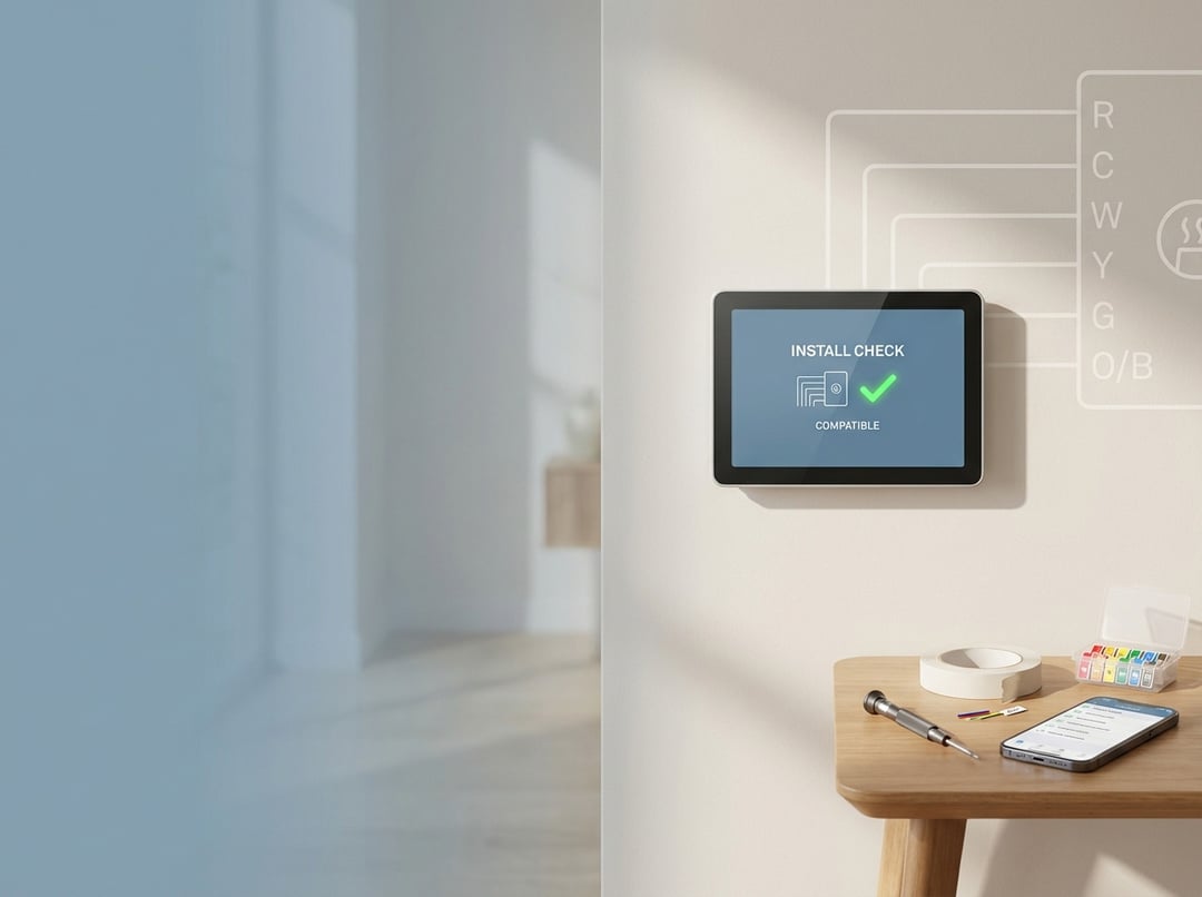
5) Run a compatibility checker as your final gate
Once you know your system type and terminals, use a manufacturer checker to catch edge cases. Nest provides compatibility guidance and a checker process to validate wiring and limitations. ecobee offers a dedicated thermostat compatibility flow that flags special scenarios early. This step costs minutes and can save you hours.
Tools and prep: reduce risk before you touch a wire
You do not need a garage full of tools. You need discipline. Gather a screwdriver set, a drill and anchors if your wall needs them, masking tape for labels, and a phone for photos. Then plan for two common failure modes.
First, people forget to cut power. HVAC control boards often include low-voltage fuses. A short can blow the fuse and create a “nothing works” situation that feels mysterious but isn’t. Second, people trust wire colors. Label by terminal instead. Consequently, your reassembly becomes deterministic rather than interpretive.
Step-by-step smart thermostat installation guide
Step 1: Turn off power and verify the system will not start
Turn off the breaker to the furnace or air handler, or use the HVAC service switch if present. Then confirm the system will not run. Some equipment delays starts, so wait long enough to avoid false confidence. Nest explicitly advises shutting off power before wiring work.
Step 2: Remove the old thermostat and document terminals and jumpers
Pull the thermostat faceplate off. Do not disconnect anything yet. Photograph the terminals. Look for jumper wires. A jumper looks like a short wire bridging two terminals, often between Rc and Rh on older thermostats. Many smart thermostats handle bridging internally, so you should not treat a jumper as a “real HVAC wire.” Nest guidance also notes not to treat jumpers as input for compatibility checks.
Step 3: Label each wire by terminal and prevent it from slipping into the wall
Place masking tape flags on each wire and write the terminal label. Then gently loosen terminal screws and pull wires free. Keep wires accessible by bending them into small hooks. This tiny habit prevents the classic “wire disappears into the wall cavity” problem.
Step 4: Mount the new backplate and route wiring cleanly
Hold the new backplate against the wall and check alignment. Level it by eye or with a level. Avoid overtightening screws because warped plastic plates create misalignment and stress on terminals. Route wires through the center opening, then keep enough slack for neat connections without bunching.
Step 5: Connect wires to the correct terminals on the new thermostat
Match wires to terminals based on your labels. Typical terminals include:
- R/Rc/Rh: 24V power feed. Some systems have one R wire. Some have separate Rc and Rh.
- C: common wire for power.
- W/W1/W2: heating calls.
- Y/Y1/Y2: cooling or compressor calls.
- G: fan relay.
- O/B, Aux/E: heat pump controls.
If you have both Rc and Rh, follow the thermostat’s instructions precisely. If you have a heat pump, pay close attention to O versus B logic during setup because it controls whether the reversing valve energizes in heating or cooling. Honeywell’s guide provides a clear overview of terminal roles and common wiring patterns.
Step 6: Restore power and complete guided configuration
Snap the thermostat onto the base, restore power, and follow the app or on-device wizard. This wizard typically asks about system type, staging, and whether you have backup heat. Do not rush this part. Configuration errors can mimic wiring errors. Nest notes that setup provides customized guidance based on your wiring and system responses.
Step 7: Commission the system with a structured test sequence
Treat the first run like a mini acceptance test: 1) Fan-only test: confirms G wiring and blower control.
2) Cooling test: confirm outdoor unit engages and indoor air cools after several minutes.
3) Heating test: confirm heat source activates and supply air warms.
4) Aux heat test for heat pumps: ensure backup heat behaves correctly if present.
Consequently, you verify the whole control chain instead of celebrating after the thermostat boots.
Troubleshooting: common problems and when to stop
If the thermostat reboots, drops Wi‑Fi, or behaves erratically, suspect insufficient power. A missing C-wire often explains instability. If heating and cooling appear reversed on a heat pump, your O/B configuration often causes it. If nothing runs at all, check whether you blew a control-board fuse during wiring.
Stop and get professional help if you see communicating terminals, proprietary connectors, or anything labeled for high voltage. Nest flags high-voltage and certain wiring types as incompatible scenarios for typical DIY installs.
Post-install optimization: get the performance you paid for
A smart thermostat installation should end with comfort and efficiency, not a fancy wall ornament. Build schedules around real occupancy. Use modest setbacks that your system can recover from without running long, inefficient cycles. If your home has hot and cold rooms, consider room sensors or zoning solutions rather than forcing extreme thermostat swings. Furthermore, review runtime history in the app after a week. If you see frequent short cycles, adjust thresholds or consult an HVAC technician to check sizing and airflow.
Conclusion: install confidently by treating compatibility as the real job
Smart thermostat installation becomes straightforward when you start with a compatibility checklist and follow a disciplined workflow. Confirm 24V control voltage, identify wires by terminal labels, plan for power with a C-wire strategy, and commission the system with structured tests. Do that, and the “smart” part finally earns its name.